English
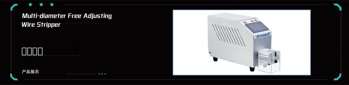

Terminal Crimping Force Standard - Kingsing Machinery Co., Limited
The quality of a crimp joint depends on the strength of the joint as well as its electrical conductivity. Crimp joint testing ensures the integrity of the final product but, more importantly, it ensures the effectiveness of the crimping tool itself, since it can be calibrated according to test results. Calibration is best carried out in response to Statistical Process Control (SPC) data which can be gathered as joint integrity degenerates over a period of time.
Pull Force Testing
-
Cut wire length to approximately 150mm (6") long.
-
Strip one end to 13mm (.50"), or long enough so no wire insulation is under the insulation grip, or loosen the insulation crimp so it has no grip on the insulation of the wire.
-
Terminate the appropriate terminal to the wire to the nominal crimp height.
-
Visually inspect the termination for bell mouth, wire brush and cut strands.
-
Set pull tester to 254mm per minute (1.00" per minute). For most applications, a higher rate will not have a significant impact on the data. The slower rate prevents a sudden application of force or jerking that snaps strands. Verify higher pull rates with data taken at 1.00” per minute.
-
If necessary, knot the un-terminated end of the wire (If insulation slips on wire).
-
Regardless of pull tester type, both wire and terminated end must be securely clamped. (Note: Clamp terminal contact interface, do not clamp conductor crimp)
-
Activate pull test.
Note: High variability and lower value of Cpk (see section 8 for explanation of Cpk) are common when two wires are crimped together. The variability is due to more variation in conductor brush, conductor bell mouth and fewer strands of one wire being in contact with the serrations on the terminal barrel. A double wire crimp is considered no better than the smallest wire crimped. Higher pull force readings can be seen if both wires are gripped and pulled exactly together. Pulling each wire individually will result in a much lower pull force reading. If both wires are of the same size, the top wire will normally result in a lower reading than the bottom wire due to the effects of the terminal serrations.
-
a. Record pull force readings. A minimum of five pull force measurements should be done to confirm each set-up. A minimum of 25 readings should be taken for determining process capability.
-
b. Compare lowest reading to minimum pull force specification.
Wire Chart
Note: Pull force has only a minimum specification. For Cpk calculations, the average reading is assumed nominal and the upper specification limit is set so Cp and Cpk are equal. High pull force readings that increase the standard deviation can lower Cpk even if the mean and lowest reading are increased.
| Test Values for Pull Force Test (UL486A) | |||
| Size of Conductor | Pullout Force | ||
| AWG | mm2 | Lbf | N |
| 30 | 0.05 | 1.5 | 6.7 |
| 28 | 0.08 | 2 | 8.9 |
| 26 | 0.13 | 3 | 13.4 |
| 24 | 0.20 | 5 | 22.3 |
| 22 | 0.324 | 8 | 35.6 |
| 20 | 0.519 | 13 | 57.9 |
| 18 | 0.823 | 20 | 89.0 |
| 16 | 1.31 | 30 | 133.5 |
| 14 | 2.08 | 50 | 222.6 |
| 12 | 3.31 | 70 | 311.5 |
| 10 | 5.261 | 80 | 356.0 |
| 8 | 8.367 | 90 | 400.5 |
Crimp Height Testing
-
Complete tool set-up procedure.
-
Crimp a minimum of five samples.
-
Place the flat blade of the crimp micrometer across the center of the dual radii of the conductor crimp. Do not take the measurement near the conductor bell mouth.
-
Rotate the micrometer dial until the point contacts the bottom radial surface. If using a caliper, be certain not to measure the extrusion points of the crimp.
-
Record crimp height readings. A minimum of five crimp height readings is necessary to confirm each set-up. A minimum of 25 readings is necessary to determine capability.
-
Check crimp height every 250 to 500 parts throughout the run.
Note: Crimp height is usually control charted because it is a quick, nondestructive measurement and is critical for the termination's electrical and mechanical reliability. There are three primary purposes for control charting. One, the number of setup samples is normally small, and its statistical value is limited. Two, since special cause/effects on a process are irregular and unpredictable; it is necessary to have a means of catching changes in the process as soon as they occur. This prevents having to scrap thousands of terminations after the run is over. Three and this is most important, the data is necessary to assess and improve the crimp process.

Bell Mouth and Cut-off Tab Length
| Symptom | Cause | Solution |
|---|---|---|
| Low pull force (Figure 9-6 and 9-7) |
Excessive bell mouth, no cut-off tab | Adjust track position for small cut-off tab |
| Excessive bell mouth, cut-off tab alright | Check for worn or incorrect punch tooling and replace | |
| Cut or nicked strands (Figure 9-8) |
No bell mouth and/or excessive cut-off tab | Adjust track position |
| Check for camber in terminal strip | ||
| Long cut-off tab (Figure 9-9) |
Good bell mouth and excessive cut-off tab | Check for worn cut-off and replace if necessary |
| Check for worn punch tooling, replace, and re-adjust track |

Conductor Brush and Insulation Position
| Symptom | Cause | Solution |
| Insulation under conductor crimp, good conductor brush (Figure 9-10) |
Strip length too short | Check specification, adjust strip length longer |
| Insulation under conductor crimp, long of transition area conductor brush length (Figure 9-11) |
Bench top crimping - Wire stop position incorrect | Adjust wire stop to centerof transition area |
| Wire Processing – Press position incorrect | Adjust press position away from wire | |
| Insulation under conductor crimp, short or no conductor brush (Figure 9-12) |
Strip length too short | Check specification, adjust strip length longer |
| Re-adjust wire stop position for bench top applications OR re-adjust press position for wire processing applications | ||
| Insulation edge centered in transition area, conductor brush too long (Figure 9-13) |
Strip length too long | Check specification, adjust strip length shorter |
| Re-adjust wire stop position for bench top applications OR re-adjust press position for wire processing applications | ||
| Irregular wire cut-off or strands pulled from insulation bundle | Check for worn stripping tooling | |
| Insulation edge centered in transition area, conductor brush too short (Figure 9-14) |
Strip length too short | Check specification, adjust strip length longer |
| Re-adjust wire stop position for bench top applications OR re-adjust press position for wire processing applications | ||
| Insulation edge under insulation crimp, Good or long conductor brush (Figure 9-15) |
Strip length too long | Check specification, adjust strip length shorter |
| Re-adjust wire stop position for bench top applications OR re-adjust press position for wire processing applications | ||
| Insulation edge under insulation crimp, short or no conductor brush (Figure 9-16) |
Bench top crimping - Wire stop position incorrect | Adjust wire stop to center of transition area |
| Wire processing - Press position incorrect | Adjust press position away from wire | |
| Verify operators wire placement ability | Operator training, reduce crimping rate |

Insulation Crimp
| Symptom | Cause | Solution |
|---|---|---|
| Terminal surrounds less than 88% of a large diameter wire (Figure 9-21) | Crimp too loose, not enough terminal insulation barrel | Tighten insulationcrimp height |
| Evaluate terminal | ||
| Terminal contacts less than 50% of a small diameter wire (Figure 9-22) | Too much terminal insulation barrel | Evaluate terminal |
| Insulation crimp barrels cut through insulation in o conductor strands (Figure 9-23) | Crimp too tight | Adjust insulation crimp height |
| Insulation not firmly gripping insulation, fails bend test (Figure 9-24) | Crimp too loose | Adjust insulation crimp height tighter |
Inexpensive hand tools provide no adjustment for the insulation crimp. A hand tool is intended for low volume applications. Although you are not able to adjust the insulation crimp on a hand tool, an insulation crimp, which pierces the insulation, may still be considered acceptable for many applications. This criterion only applies to hand tools due to their low speed crimp cycle. If the insulation crimp pierces the insulation, the wire strands tend to move aside without damage.

Crimp Height
| Symptom | Cause | Solution |
|---|---|---|
| Crimp height off target (Figure 9-26) |
Changed wire type vendor or stranding | Adjust toolingback to target |
| Changed insulation color or durometer | ||
| Changed crimp tooling | ||
| Changed crimp press (shut height) | ||
| Changed press type (manufacturer) | ||
| Changed terminal reel (lot code) | ||
| Changed tooling set-up | ||
| Damaged or worn tooling | Replace tooling | |
| Crimp height variability too high (Figure 9-27) |
Wire variability | Inspect incoming product |
| Terminal variability | ||
| Damaged, loose or worn tooling | Tooling replacement or tightening | |
| Measurement error | Gauge capability analysis | |
| Terminal spring-back too great, over crimping | Crimp height adjustment | |
| Cut or missing wire strands | Stripping process adjustment |

Pull Force
| Symptom | Cause | Solution |
|---|---|---|
| Wire breaks before conductor crimp - low pull force (Figure 9-29) |
Cut or nicked strands | Check the stripping process |
| Crimp height too low | Adjust crimp height | |
| Small or no bell mouth | Adjust tooling track | |
| Insulation crimp through insulation wall | Raise insulation crimp height | |
| Wire pulls out of conductor grip - low pull force (Figure 9-29) |
Crimp height too high | Adjust crimp height |
| Small or no conductor brush | Increase strip length | |
| Conductor bell mouth too big | Adjust tooling track | |
| Gold terminal application | Evaluate the terminal application | |
| Terminal material thickness too small | ||
| Light serrations on terminal | Contact your local sales engineer |