Terminal Crimping Standard - Kingsing Machinery Co., Limited
Terminal Cross Sectioning is a quality validation technique that is not new to Wire Processing. The use of cross sectioning has broadened over the past few years and cross section systems are now appearing outside of the quality lab and on the factory floor. This trend is expected to continue in the coming years. Cross section labs are expected to be as commonplace as a pull tester in most processing facilities.
In the past, quality tests of a terminal crimp were performed by only a pull tester and being a destructive test, it was a first off and spot in process inspection. But it certainly did not take in o account the inherent process variation of the crimp process itself. Later on as electrical performance demands increased, it was necessary to improve the quality inspection processes. At the same time, crimp design advanced and no longer was just pull test sufficient. Enter crimp compression. Crimp compression standards were a result of studies in o crimping and it was determined that a predictable percentage of crimp compression was needed to assure optimal electrical performance. Crimp Height is based on optimum compression of the wire during the crimp process.
With Cross Section analysis, we can now peak inside the crimp. This cross section analysis provides us with a great amount of detail in o not only the materials (wire and terminals), but how they are crimped together. Information that is used for documentation and archival purposes. An important aspect of cross section analysis is process improvement. Some of the measurements available from cross sectioning a crimp include:
- Crimp Height
- Crimp Width
- Crimp Compression
- Crimp Height to Crimp Width ratio
- Capability Studies including crimp height.
Process Improvement is a necessary component of any company who wishes to reduce their processing costs (material waste and processing time) as well as improving overall productivity. Cross Section analysis can be a valuable tool in process improvement. For example, crimp monitor alarms. Crimp monitors signal an alarm when an element of crimp quality causes excess variation. Often the suspect parts appear normal and acceptable. Production continues. Later on another alarm occurs. Same condition. Parameters are opened up and production continues without alarms. But the underlying problem still exists. Once this cycle starts, the monitoring system becomes less sensitive and at some point only gross errors can be detected. And the risk of accepting defective parts also increases.
Cross Sectioning a crimp offers one way of detecting an issue that could be quickly assessed and a resolution put in place. See the illustrations below.

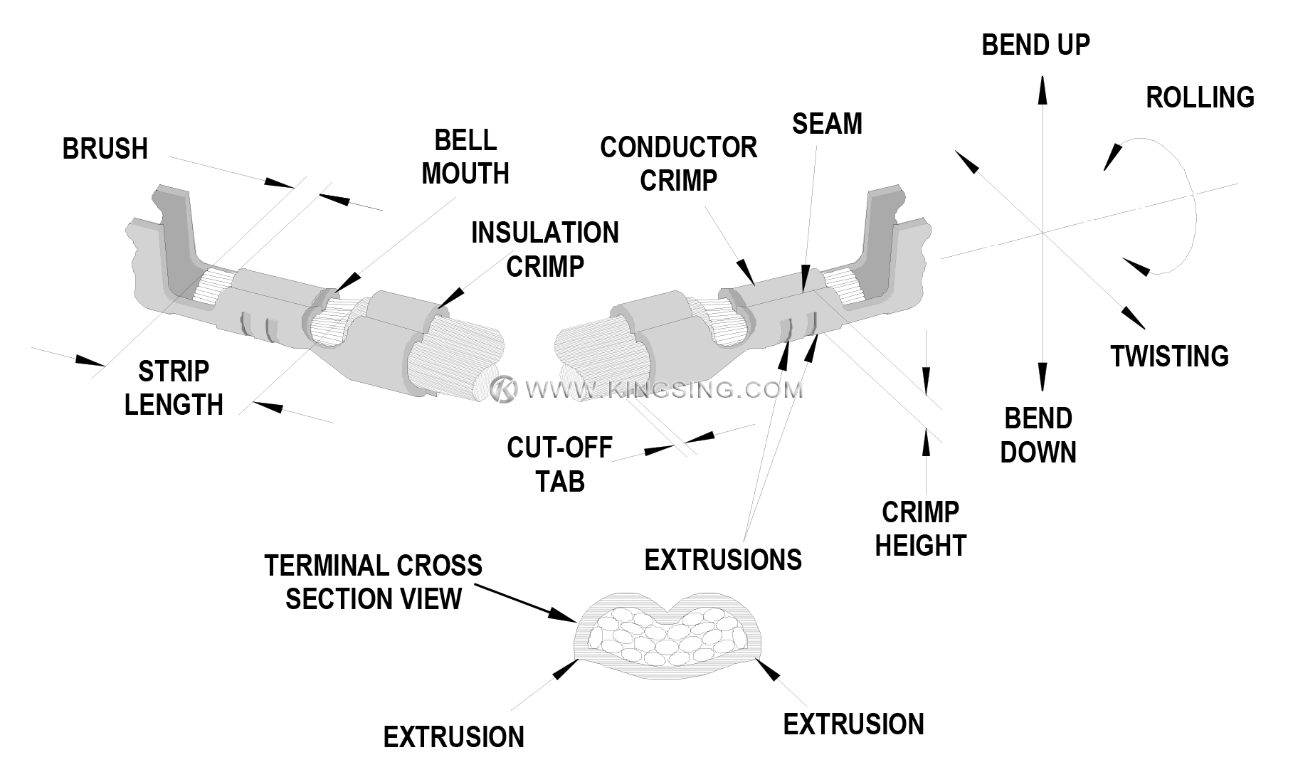
Anatomy of a Crimp Termination
-
Bell Mouth (Flare)
The flare that is formed on the edge of the conductor crimp acts as a funnel for the wire strands. This funnel reduces the possibility that a sharp edge on the conductor crimp will cut or nick the wire strands. As a general guideline, the conductor bell mouth needs to be approximately 1 to 2 times the thickness of the terminal material.
-
Bend Test
One way to test the insulation crimp is by bending the wire several times and then evaluating the movement of the insulation and wire strands. As a rule, the insulation crimp should withstand the wire being bent 60 to 90 degrees in any direction, several times. Use care when working with small wire sizes so the wire at the back of the insulation crimp does not shear.
-
Conductor Brush
The conductor brush is made up of the wire strands that extend past the conductor crimp on the contact side of the terminal. This helps ensure that mechanical compression occurs over the full length of the conductor crimp. The conductor brush should not extend in o the contact area.
-
Conductor Crimp
This is the metallurgical compression of a terminal around the wire's conductor. This connection creates a common electrical path with low resistance and high current carrying capabilities.
-
Conductor Crimp Height
The conductor crimp height is measured from the top surface of the formed crimp to the bottom radial surface. Do not include the extrusion points in this measurement (See Figure 4-1). Measuring crimp height is a quick, non-destructive way to help ensure the correct metallurgical compression of a terminal around the wire's conductor and is an excellent attribute for process control. The crimp height specification is typically set as a balance between electrical and mechanical performance over the complete range of wire stranding and coatings, and terminal materials and plating. Although it is possible to optimize a crimp height to individual wire stranding and terminal plating, one crimp height specification is normally created.
-
Cut-off Tab Length
This material protrudes outside the insulation crimp after the terminal is separated from the carrier strip. As a rule, the cut-off tab is approximately 1.0 to 1.5 times terminal material thickness. * A cut-off tab that is too long may expose a terminal outside the housing or it may fail electrical spacing requirements. In most situations, a tool is set-up to provide a cut-off tab that is flush to one materialthickness.
-
Extrusions (Flash)
These small flares form on the bottom of the conductor crimp resulting from the clearance between the punch and anvil tooling. If the anvil is worn or the terminal is over-crimped, excessive extrusion is the results. An uneven extrusion may also result if the punch and anvil alignment is not correct, if the feed adjustment is off, or if there is insufficient/excessive terminal drag.
-
Insulation Crimp (Strain Relief)
This is the part of the terminal that provides wire support for insertion in o the housing. It also allows the terminal to withstand shock and vibration. The terminal needs to hold the wire as firmly as possible without cutting through to the conductor strands. The acceptability of an insulation crimp is subjective and depends on the application. A bend test is recommended to determine whether the strain relief is acceptable for each particular application.
-
Insulation Crimp Height
Kingsing does not specify insulation crimp heights because of the wide variety of insulation thickness, material, and hardness. Most terminals are designed to accommodate multiple wire ranges. Within the terminal’s range, the strain relief may or may not completely surround the diameter of the wire. This condition will still provide an acceptable insulation crimp for most applications.
To evaluate the insulation crimp section, cut the wire flush with the back of the terminal. Once the optimum setting for the application is determined, it is important to document the insulation crimp height. Then, as part of the setup procedure, the operator can check the crimpheight.
-
A large strain relief should firmly grip at least 88% of the wire.
-
A smaller strain relief should firmly grip at least 50% of the wire and firmly hold the top of thewire.
-
Insulation Position
This is the location of the insulation in relation to the transition area between the conductor and insulation crimps. Equal amounts of the conductor strands and insulation needs to be visible in the transition area. The insulation position ensures that the insulation is crimped along the full length of the insulation crimp, and that no insulation is crimped under the conductor crimp. The insulation position is set by the wire stop and strip length for bench applications. For automatic wire processing applications, the insulation position is set by the in/outpress adjustment.
-
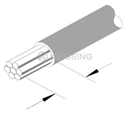
Strip Length
The strip length is determined by measuring the exposed conductor strands after the insulation is removed. The strip length determines the conductor brush length when the insulation position is centered.
-
Process
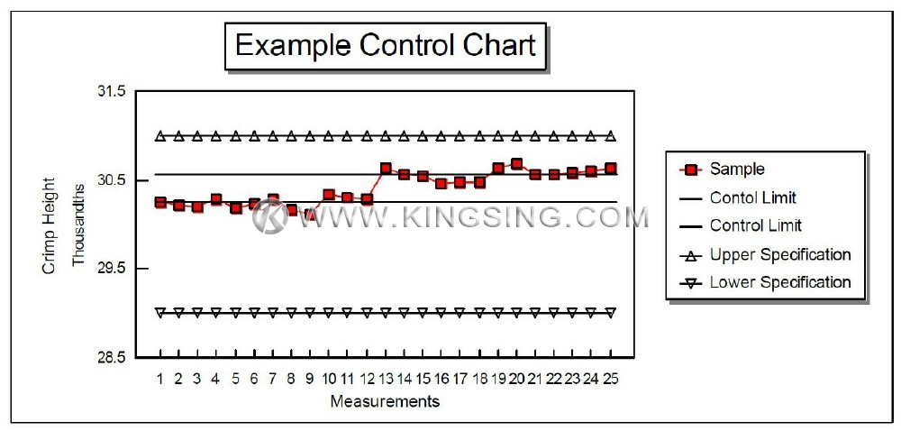
The combination of people, equipment, tooling, materials, methods, and procedures needed to produce a crimp termination. Process Control is used to track attributes over time to aid in the detection of change to the process. Detecting a process change when it happens helps prevent many thousands of badcrimps.
-
Pull Force Testing
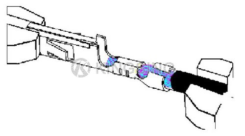
Pull force testing is a quick, destructive way to evaluate the mechanical properties of a crimp termination.
Pull force testing results out of allowed range are good indicators of problems in the process. Cut or nicked strands in the stripping operation, lack of bell mouth or conductor brush, or incorrect crimp height or tooling will reduce pull force tests results. Wire properties and stranding, and terminal design (material thickness and serration design), also can increase or decrease the value of the results of a pull force levels.
If results of a pull force tests are within an allowed range, it assures that proper crimp force has been applied during crimping. It is crucial as, when making a crimp, enough force must be applied to break down the layer of non-conductive oxides that may build up on the stripped conductor and the tinplating on the inside of the terminal grip. This is necessary to provide a good metal-to-metal contact. If this does not occur, resistance can increase. Overcrimping a crimp termination will reduce the circular area of the conductor and increase resistance.
-
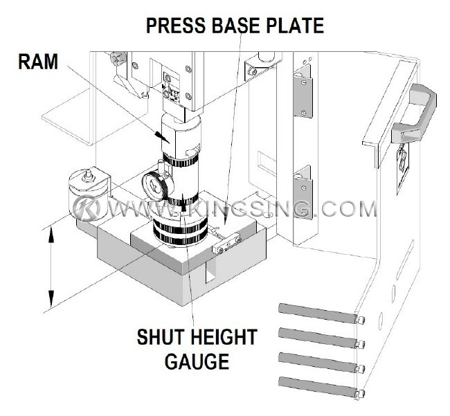
Shut Height
This is the distance (at bottom dead center on a press) from the tooling mounting base plate to the tooling connection point on the ram of the press.
-
Terminal Position
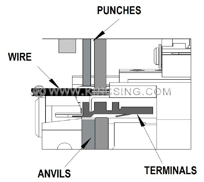
The terminal position is set by the alignment of the terminal to the forming punch and anvils, and the carrier strip cut-off tooling. The tool set-up determines conductor bell mouth, cut-off tab length, and terminal extrusions.
 English


